FAQ
Note: This definition recognizes SUE as “a branch of engineering practice”. Based on this the standard requires that SUE documents be certified by a registered professional. The tasks listed above not in italics require certification by a registered professional engineer.
The basis of standard is that designers state on the drawings, in their professional judgment, how good the utility information is deemed to be. How good the utility information is, prior to ASCE 38-02, was purely subjective. ASCE/CI 38-02 provides a clear definition for the “Quality” of the Utility information being presented on a drawing. It’s important to note that “Quality” or “Quality Level of information” as used in the standard refers to how the utility information was collected and depicted. It does not refer to quality of work or professionalism (which should always be of the highest level).
The standard refers to four quality levels (D,C,B & A) which should be referenced when depicting utilities on design and construction documents. This information indicates to all involved in a project how their roles may be affected by existing utilities and what risks they are likely to be burdened with as the project proceeds. In order for the standard to realize its full potential, owners, designers and contractors must know how to best use the information provided.
Intelligent use of the standard and appropriate incorporation of subsurface utility engineering (SUE) services will result in better designs and enhance damage prevention efforts. The standard is a comprehensive document and should be reviewed in its entirety. A significant amount of the information is also contained in Appendix A-F and should also be reviewed.
QUALITY LEVEL C: “QL-C”. Utility information obtained as above for quality level D, plotted to correlate with surface utility features which have been field verified, survey located and accurately reduced onto the design/construction documents. Included in this category are utility depictions, which in the professional opinion of the subsurface utility engineer represent the most probable approximate horizontal location, type and/or existence of a utility. Aerial utility information may also be included in this category. It should be noted that utilities, which are, typically non-linear (e.g. direct buried telephone) could be shown as QL-D even if correlated to surface utility features.
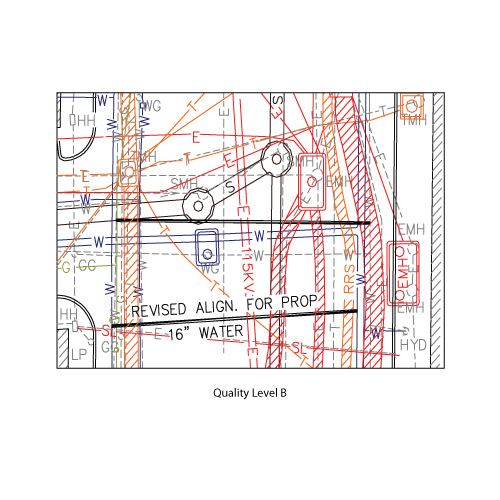
QUALITY LEVEL B: “QL-B”. Utility information derived by establishing the surface horizontal location of utility using electronic methods. Said information is subsequently field survey located and accurately reduced onto the design/construction documents.
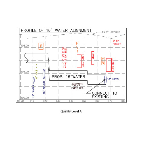
QUALITY LEVEL A: “QL-A”. Utility information which has been visually verified, survey located (both horizontally and vertically) and accurately reduced onto the design/construction documents. This Information is typically shown on a test hole data table or exploration hole log.
A study prepared by Purdue University (Publication No. FHWA-IF-00-014) for the Federal Highway Administration provides more specific information on costs verses benefits. It should be noted that the study was based on the implementation of Subsurface Utility Engineering Services (SUE) which are only partially covered by the standard.
“A savings of $4.62 for every $1.00 spent on SUE was quantified from a total of 71 projects. These projects had a combined construction value in excess of $1 billion. The costs of obtaining Quality Level ‘B’ (QL B) and Quality Level ‘A’ data on these 71 projects was less than 0.5% of the total construction costs, and resulted in savings of 1.9% percent over traditional Quality Level C (QL C) and/or Quality Level D (QL D) data.
Qualitative savings were non-measurable, but it is clear that those savings are also significant and may be many times more valuable than quantifiable savings. The figure $4.62 is somewhat less than the $7.00 to $1.00(Previous Virginia DOT study), $18.00 to $1.00(Previous Maryland DOT study), and $10.00 to $1.00(Society of American Value Engineers) returns on investment that were previously reported in the literature.
However, the quantity of studied projects is much higher; the projects are more random in nature; and no qualatative costs were included in the total. Indeed, one individual project had a $206.00 to $1.00 return on investment (North Carolina DOT). Only 3 of 71 projects had a negative return on investment.”
Electromagnetic Pipe and Cable Locators Terrain Conductivity Resistivity Methods Metal Detectors Ground Penetrating Radar Optical Methods Infrared (Thermal) Methods X-Ray Methods (Penetrating Radiation) Total Field Measurements Gradiometric Measurements Acoustic Emission Micro gravitational Techniques Isotopic (Radiometric) Techniques Chemical Techniques Borehole Geophysics Geophysical Diffraction Tomography
While all the above methods are valid, many have limitations based on cost, site conditions, limited application and current state of development. Based on a survey of Subsurface Utility Engineering Professionals it appears that at least 70% of Quality Level B data is generated using Electromagnetic Pipe and Cable Locators with other methods being used to either verify the information or for situations where Electromagnetic Pipe and Cable Locators yield poor or no results. For this reason only a description of Electromagnetic Pipe and Cable Locators is provided.
The following is not a comprehensive discussion but rather a brief overview.
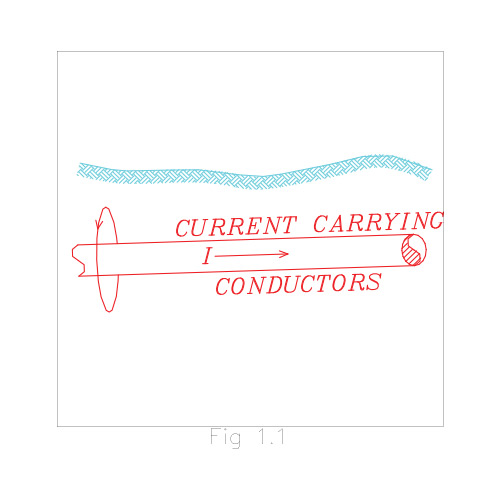
The Electromagnetic and Radiofrequency line locators operate by locating either a background signal (an ambient energy field) (see Fig 1.1) or by locating a signal introduced into the utility line using a transmitter (an applied energy field). (See Figs 1.2 & 1.3)
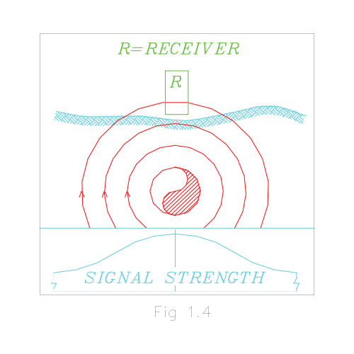
The signal carried by the utility line can be located horizontally on the surface using a receiver. The receiver is moved across the estimated location of the utility line. The location of the highest signal strength is marked as the approximate horizontal location of the utility.
The receiver is then rotated until the highest signal strength is achieved. This will give the approximate orientation of the utility. (See Figure 1.4) The approximate vertical locations can be estimated using the above techniques. In some situations, however, errors can be introduced that render the vertical location no better than good judgment would predict.
In addition, errors can occur in situations when lines are running one on top of the other. What results is a combined field, which would indicate a single utility with greater depth than the actual depth. See Figure 1.5 Conversely, the presence of a conductor above the utility being traced could lead to a shallower depth than actual. Situations such as these make the determination of vertical location with these techniques unreliable.
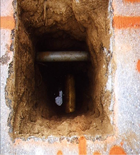
The best way to determine the vertical location is to expose the utility using minimally intrusive methods. [click image to zoom]


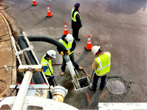
As discussed above this is because, to date, depth can not be reliably determined electronically. Exposure of the utility is by non-intrusive methods such as hand excavation or typically for SUE firms Vacuum Excavation. Survey is by usual field survey methods.[click image to zoom]
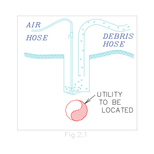

The process continues untilthe utility is uncovered. (See Figure 2.1) It should be noted that certain soil conditions may warrant the use of water jets in place of air jets however it is outlawed in certain areas due to pavement, corrosion and damage problems. The following information can typically be recorded: utility, material, size, depth, condition, location (x, y, and z), orientation, roadway section materials and depths, soil type and water table. Soil samples can be taken during the air-vacuum excavation process.
Air-vacuum excavation can be used to obtain soil samples from utility line trenches without risking damage to the utility (See Figure 2.2) which can be very useful as contaminants frequently move along utility line trenches. [click image to zoom]
The example below is somewhat of an oversimplification. The Subsurface Utility Engineer will take into consideration such things as importance of a utility, age of a utility, ease of relocation, cost of relocation, delays caused by relocation and safety issues relating to relocation.
The following example however illustrates some basic concepts. Typically a base topographic plan is prepared using conventional survey methods and/or aerial mapping. Available utility record information is then added to the drawings. This corresponds to quality level D information or quality level C information if correlated to surface utility features.
The existing utilities are electronically located and the results plotted on the base plans (quality level B). The location of the preliminary alignment is revised to avoid conflicts with existing utilities where possible. In this example the original horizontal alignment would have unnecessarily impacted several underground utilities and utility structures. Based on the revised alignment and the existing utilities, locations are chosen where exact horizontal and vertical information will be determined (quality level A).
When the quality level A data is obtained it is plotted on a profile showing exact utility locations and sizes. Now that the exact horizontal and vertical location has been established the proposed utility line can now be designed to minimize the impact on existing facilities. Where relocations are required, informed decisions can be made as to how this can be achieved.

- To determine what existing utilities exist and their specific location.
- To determine how the existing utilities will be impacted by the proposed improvements.
- To determine what measures can be taken if any to limit the impact and thereby reduce design and construction costs, construction delays and risk of damage during construction.
The above is achieved as follows:
- Generation of a Subsurface Utility Engineering deliverables which depicts the existing utilities at Specific Quality Levels (see quality level information index below).
- Comparing the SUE deliverables with the proposed work to determine impacts.
- Determine what measures need to be taken to avoid or mitigate project impacts.
- Where deemed cost effective modify the design drawings to reduce impacts. Where impacts are unavoidable the design drawing should indicate how they are to be dealt with by the contractor. In addition the pay item list / cost estimate should include items to deal with re-locations or protection of existing utilities. Re-locations “By Others” should be indicated on the drawings with a schedule and proposed location so as to ensure relocated utilities are not damaged during construction or cause project delays.
- Incorporate the SUE deliverables into the construction documents (to supersede other utility plans) for use by the contractor in determining the bid and to reduce the likelihood of damage during construction.
The simple answer is yes a Subsurface Utility Engineering provider can provide a 100% guarantee and be held liable for anything found that’s not shown on the SUE deliverable.
The question now becomes how much is it going to cost. Going back to the definitions of quality level, a 100% guarantee or full acceptance of liability comes only when quality level information is requested and provided although this may be more of an issue of insurance clauses than the ASCE standard. Quality level A information can only be obtained by, referring back to the standard, “Exposure and survey of the utility at each specific location.”
To prove the non-existence of utilities exposure is also necessary. An example of this is exposure of proposed boring locations using vacuum excavation to ensure that utilities are not damaged. So providing a 100% guarantee for a particular area requires exposure of the entire area using non-intrusive methods. This leads to costs far and above the potential savings and reduced risk of damage.